Designing switching supplies for embedded electronics with circuit protection
Whenever we want to design a new circuit or a new PCB, the first thing which we usually start with is getting that 5V or 3.3V. For many of us, a simple 7805 or LM317 will do the job, but when you need higher current (anything above 200-300mA) it’s time to go for a switching supply.

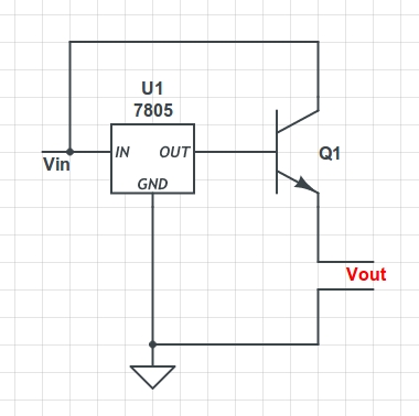
I know at first it might sound like a difficult task, but with all the software out there, it does not take much time to design a switching supply. At first I thought about ways in which I can use that simple circuitry of a 7805. Maybe add a transistor like shown here.
But then to get current like 2A, I would need a BIG transistor. Also, the voltage would not be exactly 5V, it would be 5-Vbe (forward voltage drop at the base emitter junction). Of course you can use a diode between the 7805 ground and circuit ground to cancel this effect but well that doesn’t reduce the transistor size.
Another alternative would be to use those pretty heat sinks which you saw at the electronic shop. They come with a small nut and bolt so that you can mount it on your 7805. Well that’s what I did initially and the circuit still got hot. Besides, since 7805 is a LDO, once your input voltage starts going beyond 9V, you will feel the heat 🙂 .
So what we need is a noise free supply which has a wide input voltage range and is stupid-proof (by that I mean reverse voltage protection and over-current protection).
Solution: Go to texas instruments website and download their software SwitcherPro. You can also use their online tool and specify the input voltage range and current you need for your target board and it will do all the work for you. Best part, just use the products for which you can get free samples (a great help when you are prototyping) delivered at your doorstep. The advantages of a switching supply when compared to a LDO are many and it is a must for all embedded applications where battery life or power efficiency is a concern. You get a wide input voltage range, >90% power efficiency and inbuilt over-voltage and over-current protection.
Now let’s talk about the protection circuitry. Below is the list of various methods in which you can provide different types of circuit protection:
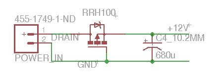
- Reverse Voltage protection: Use a p-channel MOSFET on the positive supply line of the load like shown below. You can refer more material here. I used an RRH100P03 for my circuit

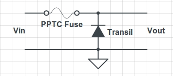
- Over-voltage, over-current and reverse voltage protection: Transient voltage suppressor diode (Transil or Tranzorb) along with a PPTC fuse should do the job. The transil protects against Over-Voltage, additionally on a reverse voltage it will get forward biased causing the PPTC Fuse to trip. Circuit as shown

- Over-current protection: PPTC (Positive polymeric temperature coefficient) fuses or resettable fuses can be used to avoid the necessity of changing fuses which are blown. As the current goes up the fuse starts heating up and its impedance increases. After a certain limit or trip point, the impedance is high enough to cut off the flow of current. The fuse is now in a tripped state. As soon as the current reduces the temperature reduces and the fuse gets reset. Ambient temperature does affect operation and you can read more about it here
- Surge voltage protection: Using MOV (Metal oxide Varistors) is a good way to provide surge voltage protection for your circuit. However, they are quite big and mostly used if your input source is from a AC line. Read more about them here
The configuration which I prefer is a p-channel MOSFET (RRH100P03) with a DC/DC switching voltage regulator (TPS5450 which has inbuilt over-current and over-voltage protection).
