Wiring diagrams for a FSAE race car (ORI2010)
In the year 2010, I was the electronics team captain for Orion Racing India (A student team which designs a formula style race car to compete in an international design competition: Formula Student Germany). Among the many responsibilities which came with being an electronics team member (apart from fixing the lighting and fans in the workshop), a very basic yet extremely important was laying the wiring for the car. Me and my teammates: Nikhil, Nathanael, Hemen, Gaurang and Anup initially tried to look for some software for making the wiring diagrams. However, a pen and a paper proved to be the best tools.
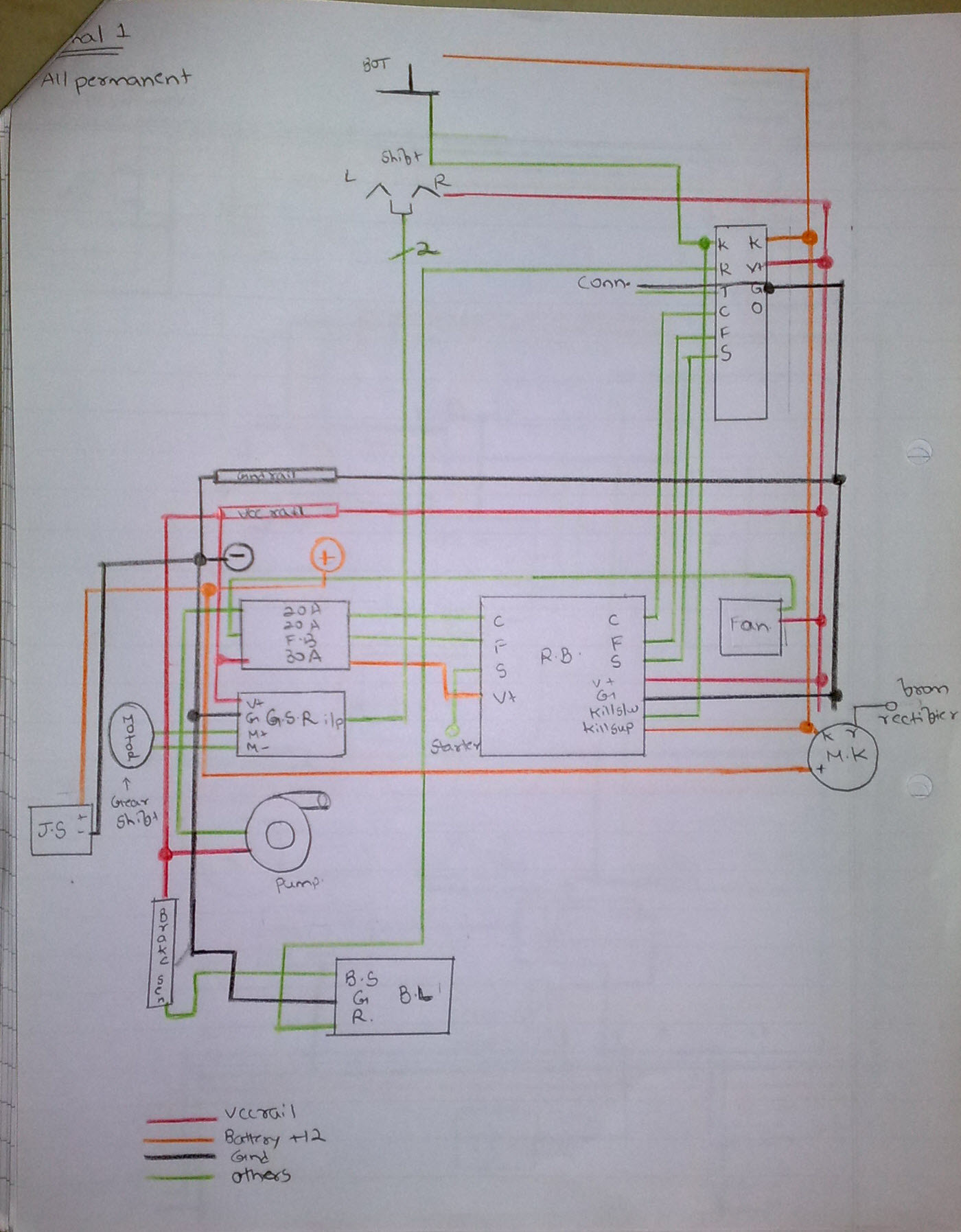
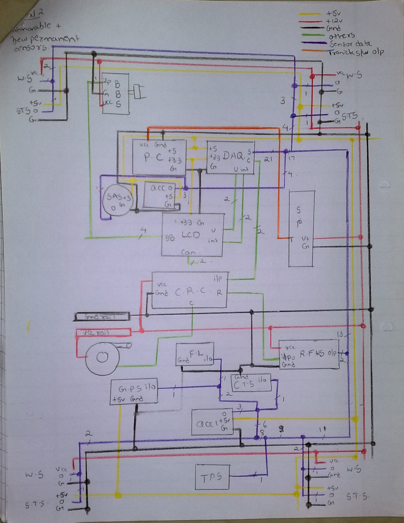
I am sharing below the final wiring diagrams and block descriptions for the ORI2010. Before arriving at the final layout, we had to go through multiple revisions. At each stage of the revision we were able to reduce/re-route many wires. Additionally, wiring diagrams helped us in quick troubleshooting and hassle free insertion/removal of sensors/modules.
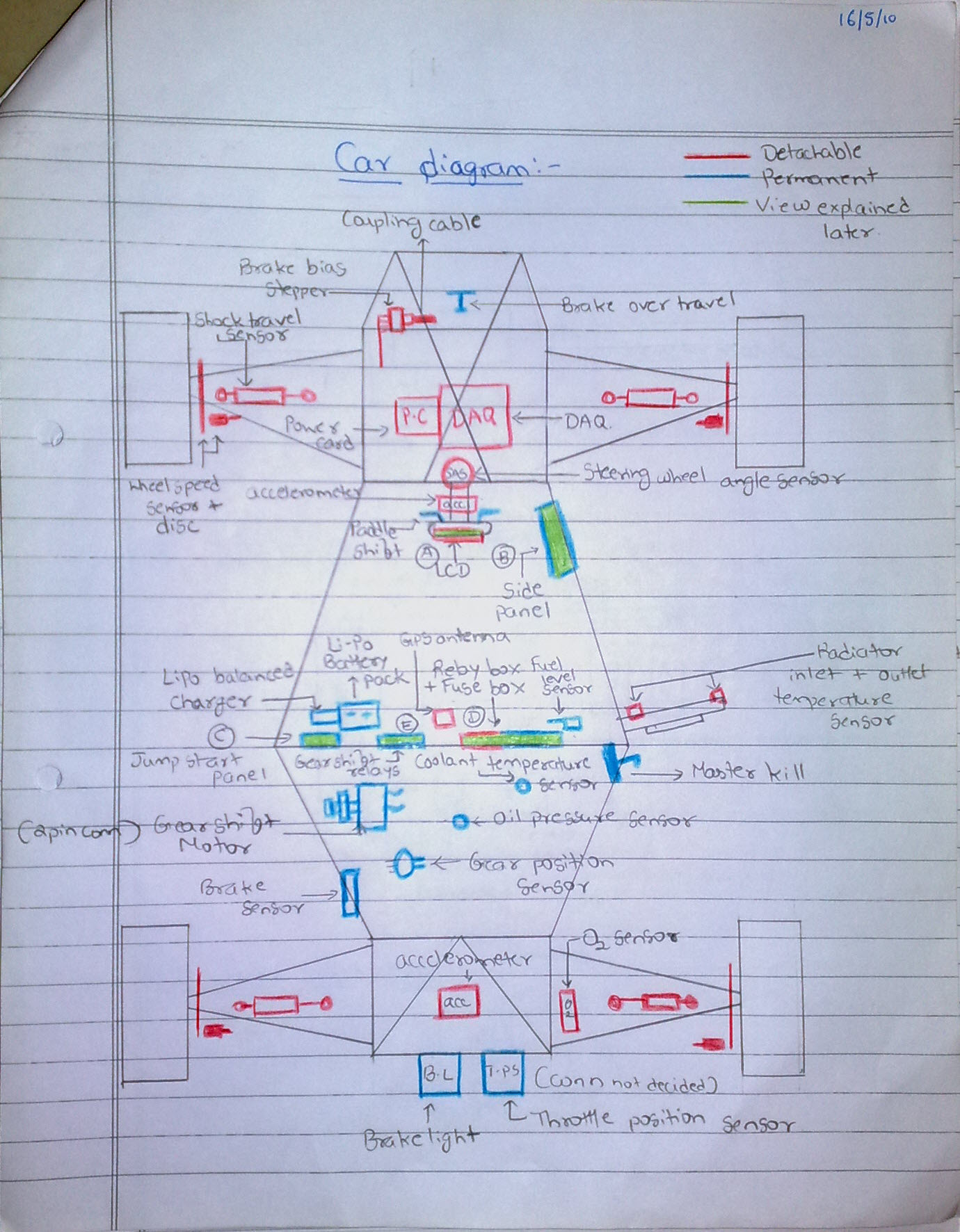
You may find many acronyms being used in the component placement as well as the wiring layouts. Their descriptions are provided in the images that follow. (Open images in a new tab for better resolution)
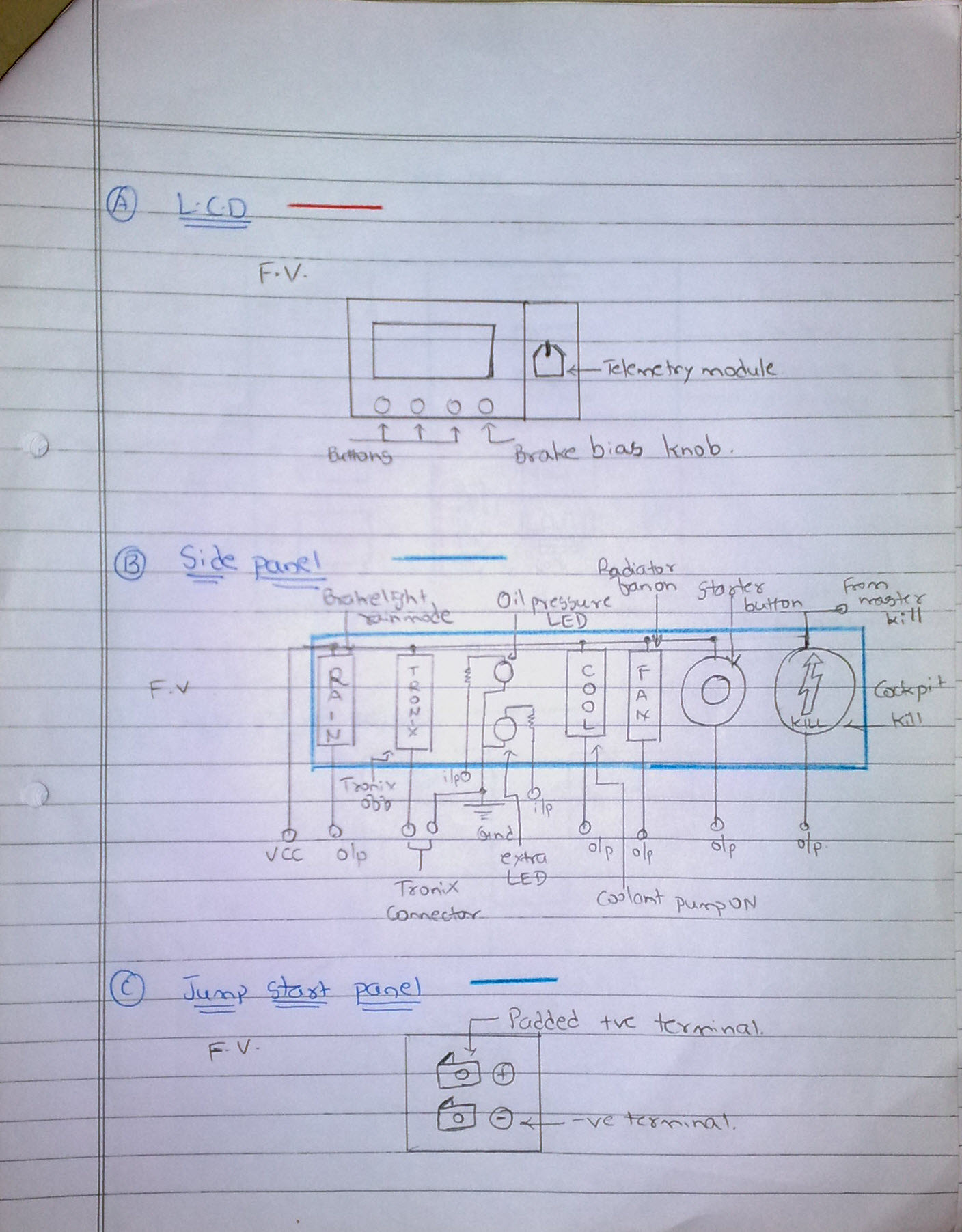
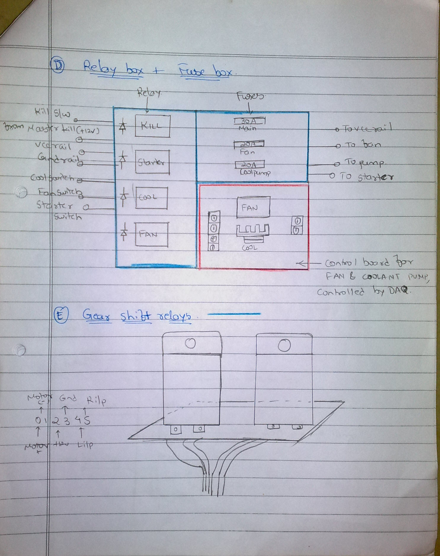
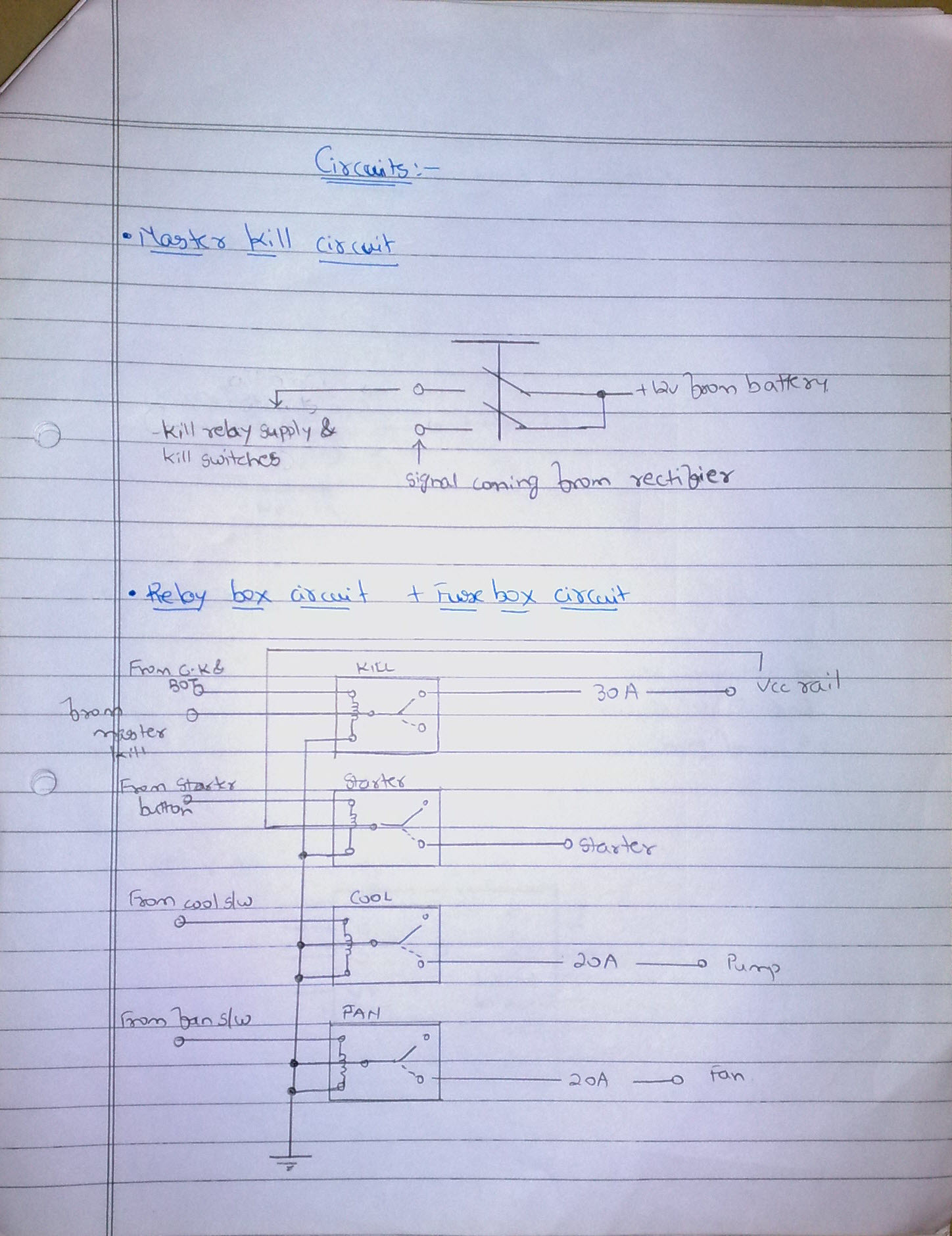
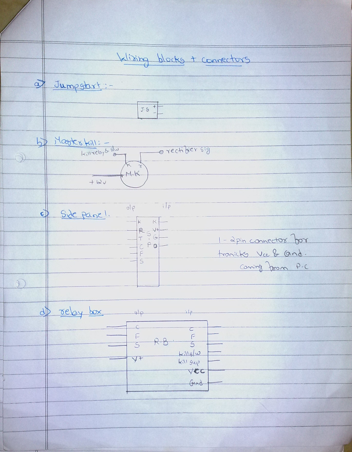
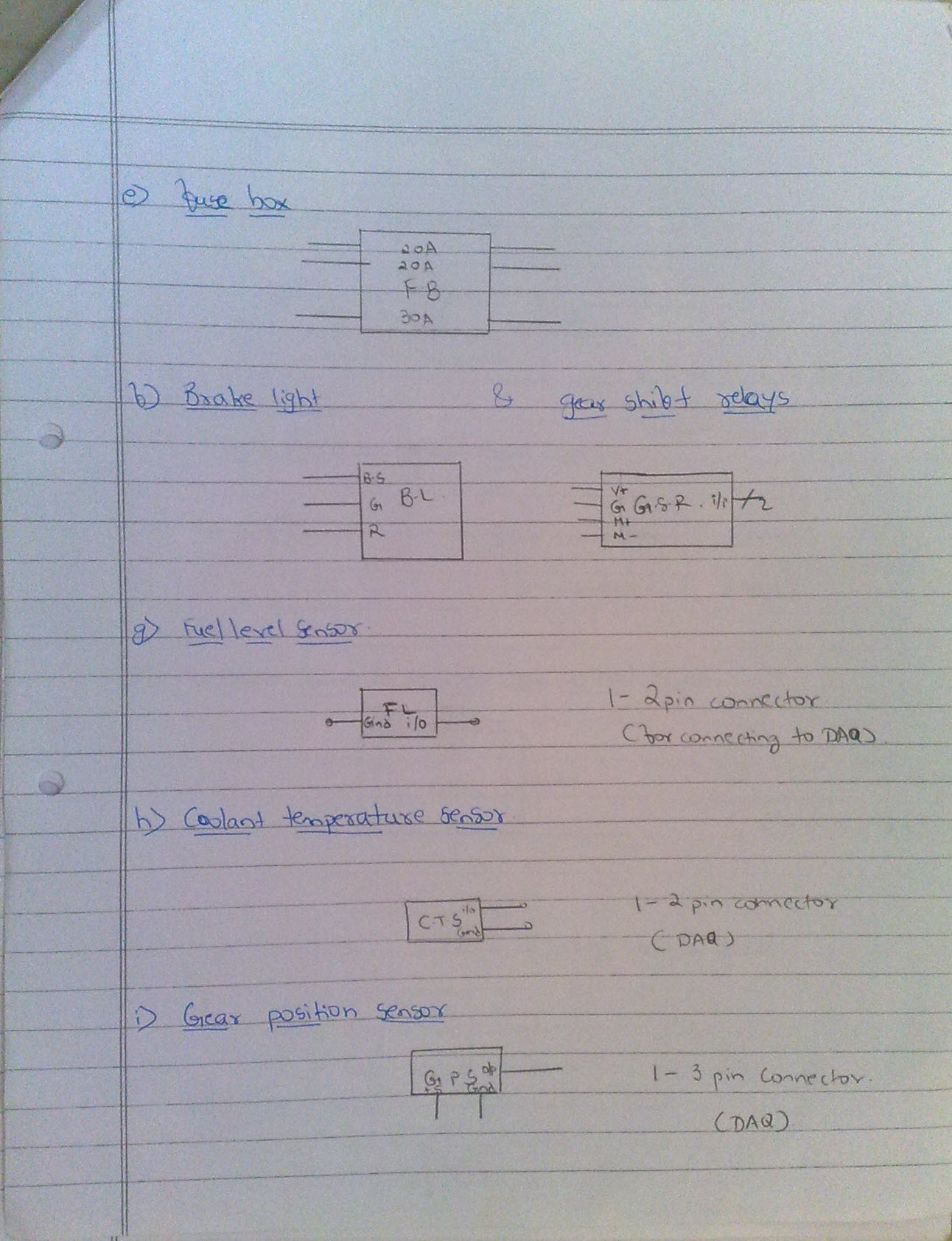
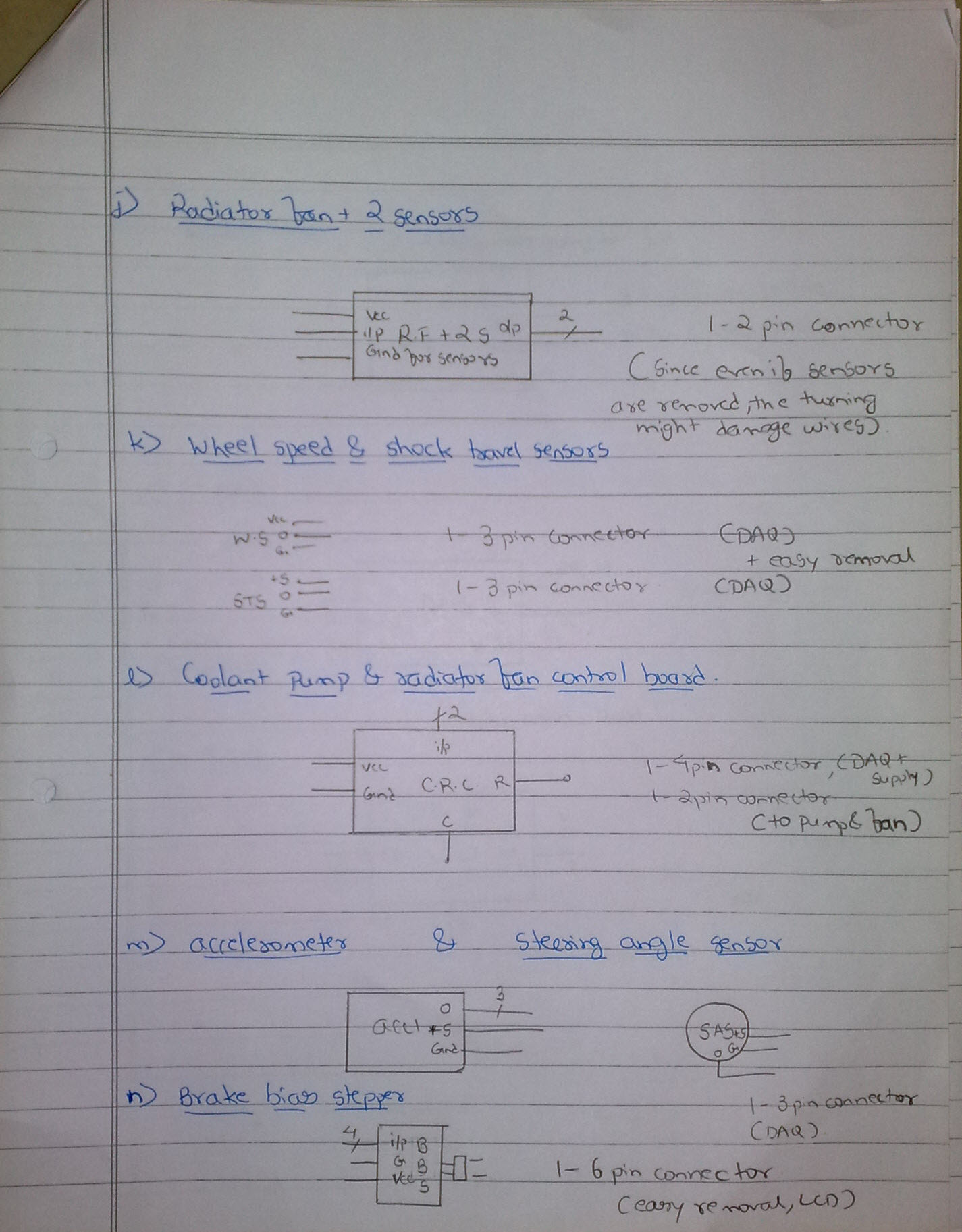
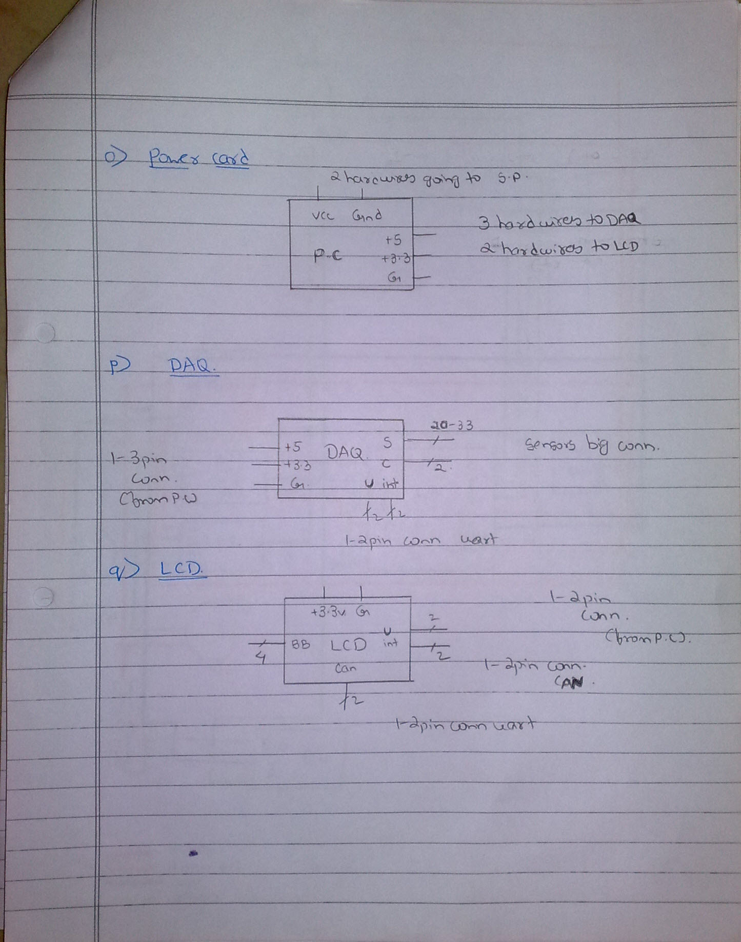
Tie wires proved to be quite useful when we were laying the wiring. One could easily unwind them and add/remove wires. Once the layout on the car was complete, we replaced the tie wires with cable ties.